I've made a previous post about Specific Impulse, but I've wanted to improve it for a while, since it's not very clear. This post is using a new system called MathJax to display equations, which should make them easier to read.
Specific impulse is essentially a measure of how efficiently a rocket engine converts the chemical potential energy of its fuel into the kinetic energy driving the rocket forward. It is defined as the thrust of a rocket engine $T$ divided by the weight flow rate $\dot{W}$: $$I_{sp}=\frac{T}{\dot{W}}$$ First, we need to distinguish between weight and mass. Mass is how much matter an object consists of, while weight is the force exerted on an object by the local gravitational field. The local gravity on Earth exerts 9.81 m/s^2 of acceleration on everything, so if force = mass times acceleration, the force, or weight, exerted by an object with 1 kg of mass is 1 kg * 9.81 m/s^2. Since one Newton is the amount of force needed to accelerate one kg at 1 m/s^2, the object has a weight of 9.81 N. Weight is normally measured in kilograms (or pounds, but they're the same dimensionally), which seems odd, since we know weight can change independently of mass on different planets with different gravities. This is because the unit commonly referred to by a kilogram is actually kilogram-force, or a kilopond, which is exactly the force of one kilogram of mass in standard Earth gravity, or about 9.81 N. Therefore, in common use, both the definition and unit of mass and weight are the same.
Specific impulse $I_{sp}$ is defined as the thrust $T$ produced by a rocket engine, divided by the weight flow rate of propellant $\dot{W}$, or: $${I_{sp}}=\frac{T}{\dot{W}}$$ It seems like it should be thrust per unit weight of propellant consumed, but thrust is instantaneous, so it wouldn't make sense without converting to some weird unit like newton-seconds.
Since $\dot{W}$ is weight, and weight is mass multiplied by standard gravity, the weight flow rate is the mass flow rate $\dot{m}$ multiplied by gravity: $$\dot{W}=g\dot{m}$$ The mass flow rate is the first derivative of the propellant mass $m_p$ with respect to time: $$\dot{m}=\frac{dm_p}{dt}$$ Therefore: $$\dot{W}=g\frac{dm_p}{dt}$$
Thrust is simply the exhaust velocity of the propellant from the engine $v_e$ multiplied by the mass flow rate $\dot{m}$ which is exactly the same as the mass flow rate already defined: $$T=v_e\frac{dm_p}{dt}$$
If we substitute these back into the original $I_{sp}$ formula, we get: $$I_{sp}=\frac{v_e\frac{dm_p}{dt}}{g\frac{dm_p}{dt}}$$ Since the mass flow rate is on both the top and bottom of the equation, we can get rid of them, and get: $$I_{sp}=\frac{v_e}{g}$$ The important thing to remember here is that $g$ is a constant in this equation. It is quite literally the acceleration due to gravity at the earth's surface, regardless of where the rocket engine is, or what kind of gravity it is in. In fact, any constant with the unit of $m/s^2$ would work. Not only that, but when calculating $\Delta{V}$ using a specific impulse term, as is frequently seen, the specific impulse term is multiplied by $g$, turning the term back into $v_e$. Another weird effect of this is that specific impulse has a unit of seconds.
This weird definition was originally used, as far as I can tell, because the unit of seconds is the same whether you're using metric or imperial units to calculate it, which is less confusing than m/s and ft/s. Using metric units, exhaust velocity and specific impulse can be calculated approximately by multiplying or dividing by ten. In short, specific impulse is a way of making exhaust velocity, which is the real measure of rocket engine efficiency, into a number which is the same whatever units you use to calculate it.
Interestingly, $v_e$ is effective exhaust velocity, which takes into account any propellant not exhausted at the full velocity of the engine, such as with turbine exhaust or film cooling. Effective exhaust velocity can be calculated on an existing engine with the specific impulse formula by using: $$v_e=\frac{T}{\dot{m}}$$ Except $T$ and $\dot{m}$ are based on measurements of a engine rather than calculated.
Showing posts with label engine. Show all posts
Showing posts with label engine. Show all posts
Monday, May 21, 2018
Thursday, December 28, 2017
History of the Delta rocket Pt. 2: Delta-B to Delta-N
Last time we stopped our review at the first of the Delta rockets proper, the Delta-A. The Delta-B was the next variant of the Delta family, and was very similar, with a lengthened second stage and an upgraded second stage engine, the AJ-10-118D. The Delta-A used the AJ-10-118.
The AJ-10-118D burns unsymmetrical dimethylhydrazine (UDMH) as a fuel, and inhibited red fuming nitric acid (IRFNA) as an oxidizer, instead of UDMH and white fuming nitric acid (WFNA), which is what the AJ-10-118 used. Variants of the AJ-10 have been used on the Apollo program, the Space Shuttle program, and are planned to be used on the Orion program.
Fuming nitric acid is more concentrated than concentrated nitric acid (>86% vs ~68%), and WFNA is nearly pure nitric acid. It makes lab gloves burst into flames.
WFNA and IRFNA are both hypergolic with UDMH. IRFNA has slightly higher performance than WFNA, however it is also considerably more dangerous, as in addition to being corrosive to almost everything, it is also more toxic and gives off nitrogen dioxide fumes. IRFNA has an inhibitor added to prevent it from being quite as corrosive. If you want to read more about this kind of thing, I can't recommend Ignition! highly enough.
Delta-B launched nine times, with one failure. The Delta-C increased the fairing size, and used an upgraded 3rd stage. It launched 13 times, with one failure.
The Delta-D, aka the Thrust Augmented Delta, added 3 strap-on Castor I solid boosters to the first stage. The Delta-E was known as the Thrust Augmented Improved Delta, with Castor 2 solid boosters, and increased the thrust of the first stage engine, the MB-3 (in this case, MB-3-III), which is part of the LR-79 family. Some sources say that the upgrade to the MB-3-III was on the Delta-D, but most say Delta-E. The second stage was made restartable, and was enlarged, along with the fairing. The third stage was changed again, and another third stage was available as an option, with which it was known as the Delta-E1.
Delta-F would have been similar to the Delta-E, but without the solid boosters, but was never built. Delta-G was a one-off, built for just two launches, Biosatellite 1 and 2, and lacking the third stage. Delta-H was similar to the Delta-G, but without the solid boosters, but was never built. Delta-I was never built, likely to avoid confusion with a possible future Delta One. Delta-J had yet another third stage, and launched just once. Delta-K was a design for a Delta with a liquid oxygen/liquid hydrogen upper stage, and was never built.
Delta-L introduced the Extended Long Tank first stage, which was longer, and not tapered. Delta-M and -N were very similar, but with different third stages. There were variants of the Delta-M and -N, known as Delta-M6 and -N6, which had six, rather than three solid boosters.
In 1972, Delta numbering systems changed from the old letter system to a four-digit numbering system. Next time, I'll cover everything under that system.
Tuesday, February 28, 2017
Nuclear rockets
One of the most important measures of rocket engines is specific impulse, which is just how efficiently a engine burns fuel. It is almost the same thing as exhaust velocity, which is how fast the exhaust stream is going when it leaves the engine.
Most rockets use chemical engines which combine a fuel and an oxidizer to accelerate the exhaust products and provide thrust. Isps of chemical rockets max out at about 450 seconds. Nuclear thermal rockets get Isp from 900 seconds on up. This is because their exhaust velocity is not limited by the energy of a chemical reaction, as they use the heat from a nuclear reaction to accelerate hydrogen by expanding it inside the core of a reactor.
This is the simplest type of nuclear thermal propulsion, and NASA did some tests on it in the '50s and '60s. The problem is that it's performance is limited by the melting point of the reactor. There are a couple of types of nuclear thermal propulsion that avoid this problem in various ways:


It works like an easybake oven, except the lightbulb is a uranium plasma contained by a quartz vessel that doesn't melt because quartz is transparent to the majority of the radiation that is emitted, and the cake is hydrogen travelling at 20 km/s. Ages 10 and up.
Isps between 2,000 and 3,000 seconds.
Isp 4,000 to 7,000 (with fusion bombs)
Most rockets use chemical engines which combine a fuel and an oxidizer to accelerate the exhaust products and provide thrust. Isps of chemical rockets max out at about 450 seconds. Nuclear thermal rockets get Isp from 900 seconds on up. This is because their exhaust velocity is not limited by the energy of a chemical reaction, as they use the heat from a nuclear reaction to accelerate hydrogen by expanding it inside the core of a reactor.
This is the simplest type of nuclear thermal propulsion, and NASA did some tests on it in the '50s and '60s. The problem is that it's performance is limited by the melting point of the reactor. There are a couple of types of nuclear thermal propulsion that avoid this problem in various ways:
Twisted ribbon, pebble bed
By changing the shape of the fuel rods in the reactor, you can increase the heat transfer to the propellant. Twisted ribbon looks like this:

Pebble bed reactors are made out of "pebbles" of fuel that look like this;

Pulsed solid-core
This type of engine works by pulsing the power at which the reactor runs at from its normal power level to far beyond what the materials that it is made could withstand. As the temperatures are momentary, the cooling system can keep it from melting down. This is even better than it sounds, as neutrons generated while it is at maximum power will heat the propellant even further.
Liquid core
Solving the problem of preventing your reactor from melting down by designing it to run while molten! Outside-the-box thinking.
Problem include keeping your molten core from escaping with the propellent.
Isp 1,500 seconds.
Gas core
The logical extension of the liquid core design by allowing the uranium to turn not just liquid but to gas.
The problem of preventing the uranium plasma from escaping is exacerbated with gas core.
Isps 1,800 seconds to 7,000 seconds with advanced designs.
Nuclear lightbulb
It works like an easybake oven, except the lightbulb is a uranium plasma contained by a quartz vessel that doesn't melt because quartz is transparent to the majority of the radiation that is emitted, and the cake is hydrogen travelling at 20 km/s. Ages 10 and up.
Isps between 2,000 and 3,000 seconds.
Fission fragment
This skips a separate propellant entirely and uses the split atoms from the fission as propellant. The original concept used discs coated with the fuel, but a more efficient design uses ground-up fuel (around 100 nanometers) which are magnetically contained before they fission.
Isp 100,000 to 1,000,000 seconds.
Nuclear pulse
Uses nuclear bombs as propulsion, by dropping them behind a strong plate that dampens the shock and heat enough that anyone on board doesn't die. It apparently would work, and was even tested with conventional explosives. Development stopped mostly due to the nuclear test ban treaty and that this is best suited to lift spacecraft from the ground to orbit.[This] is not nuts, [this] is super-nuts-Richard Courant on viewing an nuclear pulse engine test
Isp 4,000 to 7,000 (with fusion bombs)
Nuclear salt water
This is one of the most crazy concepts for a rocket engine ever made. Its fuel is 20% enriched uranium mixed at 2% with water. It is stored in tubes coated with some kind of moderator which prevents it from reaching critical mass inside the tanks. When it is injected into the combustion chamber, the uranium reaches critical mass and begins a nuclear detonation. This can be sustained with more of the fuel being injected into the chamber. This has the advantage of the nuclear pulse engine's high efficiency, with continuous thrust and the ability to work at small scales.
Wednesday, May 18, 2016
Thrust Vector Control
I'm trying a new format for this post, sort of like a Q&A.
Q: How do rockets steer?
A: Well, in a car steering refers to both figuring out where to go (looking at the road) and the actual physical mechanism that steers the wheels and changes the direction. Which one do you mean?
Q: The physical mechanism.
A: Since rockets spend much of their time in a vacuum, the mechanism for steering must not rely on an external force, like fins do. There are three ways that spacecraft do this: 1) with small rockets pointing in different directions, called reaction control thrusters. This is Apollo's reaction control thrusters:


By National Aeronautics and Space Administration (Apollo Lunar Surface Journal (direct link)) [Public domain], via Wikimedia Commons
These are good for moving large spacecraft, but do burn a limited supply of fuel.
2) With reaction wheels. This is where large spinning flywheels are sped up and slowed down to rotate the spacecraft. These are beyond the scope of this post.
3) With thrust vector control. Thrust vector control is where you rotate the engine bell a couple of degrees, effectively making part of the engines thrust go towards rotation of the spacecraft. That is the steering losses talked about previously on this blog. Thrust Vector Control (TVC) is good for moving large spacecraft easily with minimal added weight. However, it can only work while the engines are firing.
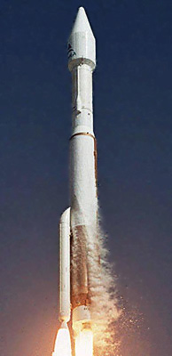
Almost all rockets use it during ascent, due to how much control authority is needed. TVC is how seemingly unstable rockets, like the Atlas 411 (http://space.skyrocket.de/img_lau/atlas-5-411__astra-1kr__2.jpg (Lockheed Martin)) or the Space Shuttle, both of which have a balance that changes a lot during flightl, are able to stay flying straight (of course, all Atlas variants are asymmetrical). The Space Shuttle has an extremely large vector range, which you can see here: https://www.youtube.com/watch?v=7Wtg_3Y4lFc
The engine rotation mechanism is called a gimbal, and uses different ways of rotating the engine. Basically, though, the engine is hinged in 2 axes above either the bell, or the entire engine. The engine is then rotated with hydraulic or electromechanical actuators. Now, you might notice that I only said 2 axes. That is because you cannot provide roll control without some kind of off-center thrust. Rockets either use multiple engines, gas generator exhaust vectoring (beyond the scope, again.), or just reaction control thrusters.
Until next time.
Q: How do rockets steer?
A: Well, in a car steering refers to both figuring out where to go (looking at the road) and the actual physical mechanism that steers the wheels and changes the direction. Which one do you mean?
Q: The physical mechanism.
A: Since rockets spend much of their time in a vacuum, the mechanism for steering must not rely on an external force, like fins do. There are three ways that spacecraft do this: 1) with small rockets pointing in different directions, called reaction control thrusters. This is Apollo's reaction control thrusters:

Credit: National Air & Space Museum, Smithsonian Institution.
And here is the Apollo CSM with the thrusters installed:

These are good for moving large spacecraft, but do burn a limited supply of fuel.
2) With reaction wheels. This is where large spinning flywheels are sped up and slowed down to rotate the spacecraft. These are beyond the scope of this post.
3) With thrust vector control. Thrust vector control is where you rotate the engine bell a couple of degrees, effectively making part of the engines thrust go towards rotation of the spacecraft. That is the steering losses talked about previously on this blog. Thrust Vector Control (TVC) is good for moving large spacecraft easily with minimal added weight. However, it can only work while the engines are firing.
Almost all rockets use it during ascent, due to how much control authority is needed. TVC is how seemingly unstable rockets, like the Atlas 411 (http://space.skyrocket.de/img_lau/atlas-5-411__astra-1kr__2.jpg (Lockheed Martin)) or the Space Shuttle, both of which have a balance that changes a lot during flightl, are able to stay flying straight (of course, all Atlas variants are asymmetrical). The Space Shuttle has an extremely large vector range, which you can see here: https://www.youtube.com/watch?v=7Wtg_3Y4lFc
The engine rotation mechanism is called a gimbal, and uses different ways of rotating the engine. Basically, though, the engine is hinged in 2 axes above either the bell, or the entire engine. The engine is then rotated with hydraulic or electromechanical actuators. Now, you might notice that I only said 2 axes. That is because you cannot provide roll control without some kind of off-center thrust. Rockets either use multiple engines, gas generator exhaust vectoring (beyond the scope, again.), or just reaction control thrusters.
Until next time.
Thursday, October 1, 2015
Rocket engines
Today we're going to look at rocket engines. Rocket engines are some of the most complex things in existence. They operate at incredible extremes, and yet they are very complex. Here's a test fire of a Merlin 1D rocket engine:
A rocket engine is very similar in concepts to a jet engine, with one difference: A jet engine collects oxidizer from the ambient air, but a rocket is completely self contained and self propelled. It carries all its fuel with it, so rocket engines have to combine fuel and oxidizer, ignite it, and propel it out at supersonic speeds.
The concepts behind rocket engines are simple, if not the implementations. A rocket is a lot like an inflated party balloon. The air in an inflated balloon is the fuel. It stretches the rubber skin, adding potential energy, and then is propelled by that energy out of the hole in the balloon, and the mass expelled from the balloon drives it across the room. Technically, a balloon is a pressure fed, monopropellant rocket.
There are a lot of kinds of rocket engines, but we'll start by looking at the most common kind: The liquid bipropellant rocket engine.
The fuel and oxidizer from the rocket's tanks are sucked from the tanks by high speed turbopumps. To give you an example, the J-2X hydrogen turbopump produces an incredible 16,000 horsepower. Where they go from there depends on the rocket. Somehow, the fuel is expanded to propel the turbo part of the turbopumps, either by being burnt with the oxidizer in a small combustion chamber and then sent to the turbopumps, if it's a gas generator cycle engine, sent around the engine to be heated up if it's an expander cycle engine, or fed through a pre-burner, which is very similar to a gas generator, except that the exhaust is fed back into the main combustion chamber to be burnt again after it's been used to power the turbopumps.
This is only a very basic overview of the different ways of dealing with turbopumps, for a more in-depth look at it see this blog's post. Actually, read all of the posts. No really, this is an great blog. All of the posts are interesting and relevant, especially to this post. Also, look at this video, from Copenhagen Suborbitals:
The fuel (and sometimes oxidizer) is then pumped through tubes in the walls of the main combustion chamber (MCC) and the nozzle walls. After that, it gets really interesting. The fuel and oxidizer is then combined and burnt in the MCC. The cold fuel flowing through the walls prevents the MCC from melting.
When fuel and oxidizer have been burnt in the MCC, the combustion products are forced out of the MCC, into the throat of the nozzle. This part is like that thing that you can put on the end of a garden hose to increase the fluid speed and decrease fluid pressure. This is known as the Venturi effect. However, the Venturi effect only works with subsonic fluids, if the fluid is supersonic, the flow "chokes" because the pressure waves that cause the Venturi effect no longer propagate upstream, instead, a diverging tube will increase speed and decrease pressure at supersonic speeds. This is the principle that makes the de Laval nozzle work, which is used in most liquid rocket engines. It is named after a Swedish inventor, Gustaf de Laval.
Here's a picture of a cross section of a de Laval nozzle:

"Laval-nozzle-(longitudinal-section-of-RD-107-jet-engine)" by Albina-belenkaya - Own work. Licensed under CC BY-SA 4.0 via Commons.
You can see how, after the exhaust has been accelerated to supersonic speeds by the nozzle converging from the MCC at the top of the picture, the nozzle diverges to further increase the speed.
Again, take a look at this blog for a more in-depth article about this.
Rocket engines are built differently for different environments. At sea level, engine nozzles are shaped differently than vacuum engine nozzles, because that the ambient pressure is higher, so nozzles need to be shaped differently to get the most thrust in the environment it's designed for.
Some rockets have hydraulic actuators which swivel the engine to provide steering while the engine's providing thrust, by changing the angle of thrust through the rocket. The hydraulic actuators are powered by the rocket engine itself. Here's a video of a J-2X engine being gimbal tested:
So how do you provide fuel to an engine that's rotating relative to the tanks? By using pipes with bellows. It seems pretty simple, except you have to remember, these pipes have less than -183 degrees Celsius liquid oxygen being forced through them, and, in some engines, even colder liquid hydrogen being pumped through them.
I'll finish this post with a video of a Copenhagen Suborbitals rocket being explained (This is a pressure fed, liquid chemical bi-propellent rocket engine):
Curious about what happened in the test? Look here.
A rocket engine is very similar in concepts to a jet engine, with one difference: A jet engine collects oxidizer from the ambient air, but a rocket is completely self contained and self propelled. It carries all its fuel with it, so rocket engines have to combine fuel and oxidizer, ignite it, and propel it out at supersonic speeds.
The concepts behind rocket engines are simple, if not the implementations. A rocket is a lot like an inflated party balloon. The air in an inflated balloon is the fuel. It stretches the rubber skin, adding potential energy, and then is propelled by that energy out of the hole in the balloon, and the mass expelled from the balloon drives it across the room. Technically, a balloon is a pressure fed, monopropellant rocket.
There are a lot of kinds of rocket engines, but we'll start by looking at the most common kind: The liquid bipropellant rocket engine.
The fuel and oxidizer from the rocket's tanks are sucked from the tanks by high speed turbopumps. To give you an example, the J-2X hydrogen turbopump produces an incredible 16,000 horsepower. Where they go from there depends on the rocket. Somehow, the fuel is expanded to propel the turbo part of the turbopumps, either by being burnt with the oxidizer in a small combustion chamber and then sent to the turbopumps, if it's a gas generator cycle engine, sent around the engine to be heated up if it's an expander cycle engine, or fed through a pre-burner, which is very similar to a gas generator, except that the exhaust is fed back into the main combustion chamber to be burnt again after it's been used to power the turbopumps.
This is only a very basic overview of the different ways of dealing with turbopumps, for a more in-depth look at it see this blog's post. Actually, read all of the posts. No really, this is an great blog. All of the posts are interesting and relevant, especially to this post. Also, look at this video, from Copenhagen Suborbitals:
The fuel (and sometimes oxidizer) is then pumped through tubes in the walls of the main combustion chamber (MCC) and the nozzle walls. After that, it gets really interesting. The fuel and oxidizer is then combined and burnt in the MCC. The cold fuel flowing through the walls prevents the MCC from melting.
When fuel and oxidizer have been burnt in the MCC, the combustion products are forced out of the MCC, into the throat of the nozzle. This part is like that thing that you can put on the end of a garden hose to increase the fluid speed and decrease fluid pressure. This is known as the Venturi effect. However, the Venturi effect only works with subsonic fluids, if the fluid is supersonic, the flow "chokes" because the pressure waves that cause the Venturi effect no longer propagate upstream, instead, a diverging tube will increase speed and decrease pressure at supersonic speeds. This is the principle that makes the de Laval nozzle work, which is used in most liquid rocket engines. It is named after a Swedish inventor, Gustaf de Laval.
Here's a picture of a cross section of a de Laval nozzle:
.jpg#/media/File:Laval-nozzle-(longitudinal-section-of-RD-107-jet-engine).jpg)
"Laval-nozzle-(longitudinal-section-of-RD-107-jet-engine)" by Albina-belenkaya - Own work. Licensed under CC BY-SA 4.0 via Commons.
You can see how, after the exhaust has been accelerated to supersonic speeds by the nozzle converging from the MCC at the top of the picture, the nozzle diverges to further increase the speed.
Again, take a look at this blog for a more in-depth article about this.
Rocket engines are built differently for different environments. At sea level, engine nozzles are shaped differently than vacuum engine nozzles, because that the ambient pressure is higher, so nozzles need to be shaped differently to get the most thrust in the environment it's designed for.
Some rockets have hydraulic actuators which swivel the engine to provide steering while the engine's providing thrust, by changing the angle of thrust through the rocket. The hydraulic actuators are powered by the rocket engine itself. Here's a video of a J-2X engine being gimbal tested:
So how do you provide fuel to an engine that's rotating relative to the tanks? By using pipes with bellows. It seems pretty simple, except you have to remember, these pipes have less than -183 degrees Celsius liquid oxygen being forced through them, and, in some engines, even colder liquid hydrogen being pumped through them.
I'll finish this post with a video of a Copenhagen Suborbitals rocket being explained (This is a pressure fed, liquid chemical bi-propellent rocket engine):
Curious about what happened in the test? Look here.
Subscribe to:
Posts (Atom)